
Kansas City, Missouri World Headquarters Web Auto Repair Database (WARD)
Education Division: Advanced Technology Career University (ATCU)
(Connecting Visions of Goals For The Future)
Advance Technology Career University U.S.A. Affiliates in Education
Tech Craftsman Career Building Trade School (TCCBTS)
Global Education Career Development, 501 (c) (3) Also Known As (GECD)
INDEPENDENT COMMERCIAL BUSINESS DIVISION: See ASSEMBLAGE OF RELATED SERVICES
In order to offer Tech Craftsman Career Building Trade School's interns/apprentices more than just going to work, becasue that's what TCCBTS is all about, 24 months, working 5 days a week and 8 hours each one of those 5 day weeks, yes, its a school but learning as if it was a job.
TCCBTS's goal is to reward our first-year interns/apprentices by expending their experiences so they can show off their skill while still going to school.
How? Easy we're going to create and develop several, Independent Commercial Businesses for the interns/apprentices to work before class or after class or both, and allowed to work on weekends and paid $15.00 dollars an hour. Now the interns/apprentices are not only earning real money, but learning on the job skill social by interacting with real customers asking for their experience and help.
INDEPENDENT COMMERCIAL BUSINESS DIVISION
Review: Assemblage of Auto Related Services to better under each individual commercial businesses. Read and Review ASSEMBLAGE OF RELATED SERVICES
Business Intellectural Concept Created by James E. Grow Library of Congress Copy(c) 2015-TXu-1-954607 Certificate of Registration
To return back to Auto Tech Internship/Apprenticeship website click below: Auto Tech Internship/Apprenticeship
2002 Isuzu Trooper LS PCM Senosr Codes
This is what's on the engine wire harness (Electrical)
Description: PCM and Sensors
The way to monitor a vehicle's electronic unit that controls one or more of the electrical systems or subsystems in a motor vehicle is through
what is referred to as (PCM), standing for Power-Train Control Module. It is an automotive unit also known as electronic control unit (ECU) that is
embedded in the car system.
The PCM is designed to do one or a few dedicated functions often with real-time computing constraints.
As I have stated, PCM is an acronym for Powertrain Control Module. It is a printed circuit board computer inside a heavy duty case, and is used
to withstand the extreme of temperatures in a vehicle's engine. The PCM monitors the vehicles' components and constantly warns the driver via
the dashboard lights if there are any problems.
58X Reference PCM Input
PCM uses this signal from the crankshaft position (CKP) sensor to calculate engine rpm and crankshaft position at all engine speeds.
This unit also uses the pulses on this circuit to initiate injector pulses. If PCM receives no impulses on this circuit, DTC PO337 will set.
Engine will not start and run without using the 58X reference signal.
A/C Request Signal
Signal tells the PCM when A/C mode is selected at the A/C control head. PCM uses this to adjust the idle speed before
turning “ON” the A/C clutch. The A/C compressor will be inoperative if this signal is not available to the PCM.
Camshaft Position (CMP) Sensor and Signal
The camshaft position sensor sends a signal the PCM. The PCM uses this signal as a (Synchronization) sync pulse to
trigger the injectors in the proper sequence. The PCM uses the CMP signal to indicate the position of the #1 piston
during its power stroke. This allows the PCM to calculate true sequential fuel injection (SFI) mode of operation.
The automotive trouble code P0342 is one of several generic malfunction codes relating to the camshaft position sensor (CPS).
Trouble codes P0335 through P0349 are all generic codes related to the CPS inferring different reasons for the failure. In this instance,
code P0342 infers the sensor's signal is to low, or not strong enough. The signal is low enough to be vague and difficult to interpret.
P0342 refers to the Bank 1 "A" sensor. Bank 1 is the side of the engine that contains cylinder #1.
Description and correlation of the crankshaft and camshaft position sensors It's important in today's vehicles to understand what these sensors
are and how they interact. All distributorless ignition vehicles use a crank and cam sensor to take the place of the module and trigger wheel found
in an electronic distributor. The crankshaft position sensor (CPS) signals the engine control module the location of the pistons relative to top dead
center in preparation for injecting fuel and firing the spark plugs. The camshaft position sensor (CMP) signals the position of the camshaft intake lobe
relative to the CPS signal and the opening of the intake valve for fuel injection on each cylinder.
Description and location of sensors The crank and cam sensors provide an "on and off" signal. Both are either hall effect or magnetic in function.
A hall effect sensor uses an electro-magnetic sensor and a reluctor. The reluctor is shaped like small cups with squares cut out of the sides making it
resemble a picket fence. The reluctor spins while the sensor is stationary and mounted very close to the reluctor. Every time a post passes in front of
the sensor a signal is produced, and when the post passes, the signal is off.
A magnetic pickup uses a stationary sensor and a magnet attached to the rotating part. Every time the magnet passes in front of the sensor a signal
is produced.
Locations
A hall effect crank sensor is located on the harmonic
balancer in the front of the engine. The magnetic pickup can be in the side of the engine block where it uses the center of the crankshaft for a signal,
or it can be in the bellhousing where it uses the flywheel as a trigger.
The camshaft sensor mounts in the front or rear of the camshaft.

If the PCM detects an incorrect (CMP) signal while the engine is running. DTC P0341 will set. If the CMP signal is lost while the engine is running,
the fuel injection system will shift to a calculated sequential fuel injection mode based on the last fuel injection pulse, and the engine will continue
to run, a long as the fault is present, the engine can be restarted.
long as t he fault is present, the engine can be restarted. It will run in the calculated sequential mode with a 1-in-6 chance of the injector sequence
being correct.
Engine Coolant Temperature (ECT) Sensor

The ECT sensor is a thermostat (a resistor which changes value based on temperature) mounted in the engine coolant steam. Low coolant
temperature produces a high resistance of 100,000 ohms at -40°C (-40°F). High temperature causes a low resistance of 70 ohms at 130°C (266°F).
The PCM supplies a 5-volt signal to the ECT sensor through resistors in the PCM and measures the voltage. The signal voltage will be high when the
engine is cold and low when the engine is hot. By measuring the voltage, the PCM calculates the engine coolant temperature. Engine coolant
temperature affects most of the systems that the PCM controls.

Tech 2 displays engine coolant temperature in degrees. After engine start-up, the temperature should rise steadily to about 580176C (85°F).
It then stabilizes when the thermostat opens. If the engine has not been run for several hours (overnight), the engine coolant temperature and intake
air temperature displays should be close to each other. A hard fault in the engine coolant sensor circuit will set DTC P0177 or DTC P0118.
An intermittent fault will set a DTC P1114 or P1115.
Electrically Erasable Programmable Read Only Memory
The electrically erasable programmable read only memory (EEPROM) is a permanent memory chip that is physically soldered within the PCM.
The EEPROM contains the program and the calibration information that the PC needs to control powertrain operation.

Unlike the PROM used in past applications, the EEPROM is not replaceable. If the PCM is replaced, the new PCM will need to be programmed.
Equipment containing the correct program and calibration for the vehicle is required to program the PCM.
Fuel Control Heated Oxygen Sensors
Bank 1 HO2S 1 and (Bank 2 HO2S 1) are mounted on the exhaust steam where they can monitor the oxygen content of the exhaust gas.
The oxygen present in the exhaust gas reacts with the sensor to produce a voltage output. This voltage should constantly fluctuate from approximately
100MV to 900 mV. The heated oxygen sensor voltage can be monitored with Tech f2. By monitoring the voltage output of the oxygen sensor, the
PCM calculates the pulse width command for the injectors to produce the proper combustion chamber mixture.

- Low HO2S voltage is a lean mixture which will result in a rich command to compensate.
- High HO2S voltage is a rich mixture which will result in a lean command to compensate
An open Bank 1 HO2S 1 signal circuit will set a DTC P0134 and Tech 2 will display a constant voltage between 400-500 mV. A constant voltage below
300 mV in the sensor circuit (Circuit grounded) will set DTC P0131. A constant voltage above 800 mV in the circuit will set DTC P0132. Faults in the
Bank 2 HO2S 1 signal circuit will cause DTC 0154 (open circuit), DTC P0151 (grounded circuit), or DTC P0152 (signal voltage high) to set.
Vehicle Speed Sensor (VSS)
The PCM determines the speed of the vehicle by converting a pulsing voltage signal from the vehicle speed sensor (VSS) into miles per hour.
The PCM uses this signal to operate the cruise control, speedometer, and the TCC and shift solenoids in the transmission.

Use of Circuit Testing Tools
DO NO use a test light to diagnose the powertrain electrical systems unless specifically instructed by the diagnostic procedures. Use Connector
Test Adapter Kit J35616 whenever diagnostic procedures call for probing connectors.
Aftermarket Electrical and Vacuum Equipment
Aftermarket (add-on) electrical and vacuum equipment is defined as any equipment which corrects to the vehicle's electrical or vacuum systems that is in
talled on a vehicle after it leaves the factory. No Allowance have been made in the vehicle design for this type of equipment.
NOTE: No add-on vacuum equipment should be added to this vehicle
NOTE: Add-on electrical equipment must only be connected to the vehicle's electrical system at the battery (power and ground)
Add-on electrical equipment, even when installed to these guidelines, may still cause the powertrain system to malfunction. This may also include
equipment not connected to the vehicles electrical system such as portable telephones and radios. Therefore, the first step in diagnosing any powertrain
problem is to eliminate all aftermarket electrical equipment from the vehicle. After this is done, if the problem still exists, it may be diagnosed in the
normal manner.
Electrostatic Discharge Damage
Used in the PCM are often designed to carry very low voltage. Electronic components are susceptible to damage caused by electrostatic discharge.
Less than 100 volts of of static electricity can cause damage to some electronic components. By comparison, it takes as much as 4000 volts for a person
to feel even the sap of a static discharge.
There are several ways for a person to become statically charged. The most common methods of charging are by friction and induction.
- An example of charging by friction is a person sliding across a vehicle seat.
- Charge by induction occurs when a person with well insulated shoes stands near a highly charged object and momentary touches ground.
Charges of the same polarity are drained off leaving the person highly charged with the opposite polarity. Static charges can cause damage, therefore it
is important to use care when handling and testing electronic components.
NOTE: To prevent possible electrostatic discharge damage, follow these guidelines:
- Do not touch the PCM connector pins or soldered components on the PCM circuit board.
- Do not touch the knock sensor module component leads
- Do not open the replacement part package until the part is ready to be installed.
- Before removing the part from the package, ground the package to a known good ground on the vehicle.
- If the part has been handled while sliding across the seat, while sitting down from a standing position, or while walking a distance, touch a know
good ground before installing the part.
Up-shift Lamp (Refer to Manual Transmission)
General Description (Air Induction)
Air Induction System
This system filters contaminants from the outside air, and directs the progress of the air as it is drawn into the engine. A remote-mounted air cleaner
prevents dirt and debris in the air from entering the engine. The air duct assembly routes filtered air to the throttle body. Air enters the engine by
following steps:

1. Through the throttle body.
2. Into the common chamber.
3. Through the cylinder head intake ports.
4. Into the cylinders.
General Description (Fuel Metering)
Acceleration Mode
The PCM provides extra fuel when it detects a rapid increase in the throttle position and the air flow.
Accelerator Controls
This system is a cable-type system with specific linkage adjustments. (refer to Cable Adjustment)
Battery Voltage Correction Mode
When battery voltage is low, the PCM will compensate for the weak spark by increasing the following:
- The amount of fuel delivered.
- The idle RPM.
- Ignition dwell time.
CMP Signal
The PCM uses this signal to determine the position of the number 1 piston during its power stroke, allowing the PCM to calculate true sequential
multi-port fuel injection (SFI). Loss of this signal will set a DTC PO341 trouble code. If the CMP signal is lost while the engine is running, the fuel injection
system will shift to a calculated sequential fuel injection based on the last fuel injection pulse, and the engine will continue to run.
The engine can be restated and will run in the calculated sequential mode as long as the fault is present, with a 2-in-6 chance of being correct.
Clear Flood Mode
Clear a flooded engine by pushing the accelerator pedal down all the way. The PCM then de-energizes the fuel injectors. The PCM holds the fuel injector
de-energized as long as t he throttle remains above 80% and the engine speed is below 800 RPM. If the throttle position becomes less than 80%, the
PCM again begins to pulse the injectors "ON" and "OFF", allowing fuel into the cylinders.
Deceleration Mode
The PCM reduces the amount of fuel injected when it detects a decrease in the throttle position and the air flow. When deceleration is very fast,
the PCM may cut off fuel completely for short periods.
Engine Speed/Vehicle Speed/Fuel Disable Mode
The PCM monitors engine speed. It turns off the fuel injectors when the engine speed increases above 6400 RPM. The fuel injectors are turned back on
when engine speed decreases below 6150 RPM.
Fuel Cutoff Mode
No fuel is delivered by the fuel injectors when the ignition is "OFF". This prevents engine run-on. In addition, the PCM suspends fuel delivery if no
reference pulses are detected (engine not running) to prevent engine flooding.
Fuel Injector
The sequential multi-port fuel injection (SFI) fuel injector is a solenoid-operated device controlled by the PCM. The PCM energizes the solenoid, which
open a valve to allow fuel delivery.
 The fuel is injected under pressure in a conical spray pattern at the opening of the intake valve. Excess fuel ot used by the injectors passes through the
fuel pressure regulator before being return to the fuel tank.
A fuel injector which is stuck partly open will cause a loss of fuel pressure after engine shut down, causing long crank times.
Fuel Metering System Components
The fuel metering system is made up of the following parts:
- The fuel injectors
- The throttle body
- The fuel rail.
- The fuel pressure regulator.
- The PCM
- The crankshaft position (CKP) sensor.
- The camshaft position (CMP) sensor
- The idle air control (IAC) valve.
- The fuel pump.
- The fuel pump relay.
Basic System Operation
The fuel metering system starts with the fuel in the fuel tank. An electric fuel pump, located in the fuel tank, pumps fuel to the fuel rail through and
in-line fuel filter. The pump is designed to provide fuel at a pressure above the pressure needed by the injectors. A fuel pressure regulator in the fuel rail
keeps fuel available to the fuel injectors at a constant pressure. A return line delivers unused fuel back to the fuel tank.
Fuel Metering System Purpose
The basic function of the air/fuel metering system is to control the air/fuel delivery tot he engine. Fuel is delivered to the engine by individual fuel
injectors mounted in the intake manifold near each intake valve.
The main control sensor is the heated oxygen sensor (HO2S) located in the exhaust system. The HO2A tell the PCM ho much oxygen is in the exhaust gas.
the PCM changes the air/fuel ratio to the engine by controlling the amount of time that fuel injector is "ON." The best mixture to minimize exhaust
emissions is 14.7 parts of air to 1 pat of gasoline by weight., which allows the catalytic converter to operate most efficiently. because of the constant
measuring and adjusting of the air/fuel ratio, the fuel injection system is called a "closed loop" system.
The PCM monitors signals from several sensors in order to determine the fuel needs of the engine. Fuel is delivered under one of several conditions called
"modes." All modes are controlled by the PCM.
Fuel Pressure Regulator
A diaphragm-operated relief valve mounted on the fuel rail with fuel pump pressure on one side and manifold pressure on the other side.
The fuel pressure regulator maintains the fuel pressure available to the injector at three times barometric pressure adjusted for engine load. It may be
serviced separate.
If the pressure is too low, poor performance and a DTC P0131, DTC P0151, DTC P0171, or DTC P01171 will be the result. If the pressure is too high,
excessive odor and/or a DTC P0132, DTC PO152, DTC PO172 or DTC PO175 will be the result. If the pressure is too high, excessive odor and/or a DTC PO132,
DTC PO152, DTC PO172, or DTC PO175 will be the result, (Refer ot Trouble Codes).
Fuel Pump Electrical Circuit
When the key is first turned "ON," the PCM energizes the fuel pump relay for two seconds to build up the fuel pressure quickly. If the engine is not
started within two seconds, the PCM shuts the fuel pump off and waits until the engine is cranked. When the engine is cranked and the 58X crankshaft
position signal has been detected by the PCM, the PCM supplies 12 volts tot he fuel pump relay to energize the electric in-tank fuel pump.

An inoperative fuel pump will cause a "no-start" condition. A fuel pump which does not provide enough pressure will result in poor performance.
Fuel Rail

A mounted to the top of the engine and distributes fuel to the individual injectors. Fuel is delivered to the fuel inlet tube of the fuel rail by the fuel lines.
The fuel goes through the fuel rail to the fuel pressure regulator. The fuel pressure regulator maintains a constant fuel pressure at the injectors,
Remaining fuel is then returned to the fuel tank.
Idle Air Control (IAC) Valve
The purpose of the idle air control valve is to control engine idle speed, while preventing stalls due to changes in engine load. The IAC valve, mounted in
the throttle body, controls bypass air around the throttle plate. By moving the conical valve (pintle, a pin or bolt) in (to decrease air flow) or out
(to increase air flow), a controlled amount of air can move around the throttle plate. If the RPM is too low, the PCM will retract the IAC pintle, resulting
in more air moving past the throttle plate to increase the RPM. If the RPM is to high, the PCM will extend the IAC pintle, allowing less air to move past
the throttle plate, decreasing the RPM.
The IAC pintle valve moves in small steps called counts. During idle, the proper position of the IAC pintle is calculated by the PCM based on battery
voltage, coolant temperature, engine load, and engine RPM. If the RPM drops below a specified value, and throttle plate is closed, the PCM senses a
ner-stall condition. The PCM will then calculate a new IAC pintle valve position to prevent stalls.
If the IAC valve is disconnected and reconnected with the engine running, the idle RPM will be wrong. Ins this case, the IAC must be reset. The IAC resets
when the key is cycled "ON" then "OFF." When servicing the IAC, it should only be disconnected or connected with the ignition "OFF."
The position of the IAC pintle valve affects engine start-up and the idle characteristics of the vehicle. If the IAC pintle is fully open, too much air will be
allowed into the manifold.

This results in high idle speed, along with possible hard starting and a lean air/fuel ratio. DTC PO507 or DTC PO1509 may set. If the IaC pintle is stuck
closed, too little air will be allowed in the manifold. This results in a low idle speed, along with possible hard starting and a rich air/fuel ratio.
DTC PO506 or DTC PO1508 may set. If the IAC pintle is stuck part-way open, the idle may be high or low and will not respond the changes in the engine
load.
Run Mode
Has the following two conditions:
- Open loop
- Closed loop
When the engine is first started the system is in 'open loop" operation. In "open loop," the PCM ignores the signal from the heat oxygen sensor (H02S)l.
It calculates the air/fuel ratio based on inputs from the TP, ECT, and MAF sensors.
The system remains in "open loop" until the following conditions are met:
- The H02S has a varying voltage output showing that it is hot enough to operate properly (this depends on temperature).
- The ECT has reached a specified temperature.
- A specific amount of time has elapsed since starting the engine.
- Engine speed has been greater than a specified RPM since start-up.

The specific values for the above conditions vary with different engines and are stored in the programmable read only memory (PROM). When these
conditions are met, the system enters "closed loop" operation. In "closed loop" the PCM calculates the air/fuel ratio (injector on-time) based on the
signal from the HO2S. This allows the air/fuel ratio to stay very close to 14.7:1.
Starting Mode
when the ignition is first turned "ON, " the PCM energizes the fuel pump relay for two seconds to allow the fuel pump to build up pressure.
The PCM then checks the engine coolant temperature (ECT) sensor and the throttle position (TP) sensor to determine the proper air/fuel ratio for starting.
The PCM controls the amount of fuel delivered in the starting mode by adjusting how long the fuel injectors are energized by pulsing the injector for very short times.
Throttle Body Unit
Has a throttle plate to control the amount of air delivered to the engine. The TP sensor and IAC valve are also mounted on the throttle body.
Vacuum ports located behind thee throttle plate provide the vacuum signals needed by various components.
Engine coolant is directed through a coolant cavity in the throttle body to warm the throttle valve and to prevent icing.
General Description (Electronic Ignition System)
Camshaft Position (CMP) Sensor
As the camshaft sprocket turns, a magnet in the sprocket activates the Hall-effect switch in the CMP sensor. When the Hall-effect switch is activated,
it grounds the signal line to the PCM, pulling the camshaft position sensor signal circuit's applied voltage low. This is a CMP singal. The CMP signals is
created as piston #1 is approximately 25° after top dead counter on the power stroke. If the correct CMP signal is not received by the PCM, DTC PO341
will be set.
Crankshaft Position (CKP) Sensor
Provides a signal used by the powertrain control module (PCM) to calculate the ignition sequence. The sensor initiates the 58X reference pulses which
the PCM uses to calculate RPM and crankshaft position.
Electronic Ignition
This system controls fuel combustion by providing a spark to ignite the compressed air/fuel mixture at the correct time. To provide optimum engine
performance, fuel economy, and control of exhaust emissions, the PCM controls the spark advance of the ignition system. Electronic ignition has the
following advantages over a mechanical distributor system:
 
- No moving parts.
- Loss maintenance.
- Remote mounting Capability.
- No mechanical load on the engine.
- More coil cool-down time between firing events.
- Elimination of mechanical timing adjustments.
- Increased available ignition coil saturation time.
Ignition Coils
A separate coil-at-plug module is located at each spark plug. The coil-at-plug module is attached to the engine with two screws. It is installed directly to
the spark plug by an electrical contact inside a rubber boot. A three-way connector provides 12-volt primary supply from the 15-amp ignition fuse, a
ground-switching trigger line from the PCM, and a ground.
Ignition Control
The ignition control (IC) spark timing is the PCM's method of controlling the spark advance and the ignition dwell.
The IC spark advance and the ignition dwell are calculated by the PCM using the following inputs:
- Engine speed
- Crankshaft position (58X reference).
- Camshaft position (CMP) sensor
- Throttle position (TP) sensor
- Knock signal (knock sensor).
- Park/Neutral position (PRNDL input).
- Vehicle speed (vehicle speed sensor).
- PCM and ignition system supply voltage.
- The crankshaft positron (CKP) sensor sends the PCM a 58X signal related to the exact position of the crankshaft.
- The camshaft position (CMP) sensor sends a signal related to the position of the camshaft.
- The Knock sensor tells the PCM if there is any problem with pre-ignition or detonation. This information allows the PCM to retard timing, if necessary
Based on these sensor signals and engine load information, the PCM sends 5 Volts to each ignition coil.
 
The PCM applies 5 volts signal voltage to the ignition coil requiring ignition. This signal sets on the power transistor of the ignition coil to establish a
grounding circuit for the primary coil, apply battery voltage to the primary coil.
At the ignition timing, the PCM stops sending the 5V signal voltage. Under this condition the power transistor of the ignition coil is set off to cut the
battery voltage to the primary coil, thereby causing a magnetic field generated in the primary coil to collapse, On this moment a line of magnetic force
flows to the secondary coil, and when this magnetic line crosses the coil, high voltage induced by the secondary ignition circuit to flow through the spark
plug t the ground.
Ignition Control PCM Output

6E-347
Intake Air Temperature (IAT) Sensor
The air temperature sensor is a thermostat which changes its resistance based on the temperature of air entering the engine. Low temperature produces
a high resistance of 100,000 ohms at -40°C (-40°F).
High temperature cause low resistance of 70 ohms at 130°C (266°F). The PCM supplies a 5-volt signal to the sensor through a resistor in the PCM and
monitors the signal voltage.

The voltage will be high when the incoming air is cold. The voltage will be low when the incoming air is hot. By measuring the voltage, the PCM
calculates the incoming air temperature. The IAT sensor signal is used to adjust spark timing according to the incoming air density.
Tech 2 displays the temperature of the air entering the engine. The temperature should read close to the ambient air temperature when the engine is
cold and rise as under-hood temperature increases. If the engine has been run for several hours (overnight) the IAT sensor temperature and engine
coolant temperature should read close to each other. A fault in the IAT sensor circuit will set DTC P112 or DTC P0113.
Electrically Erasable Programmable Read Only Memory
The electrically erasable programmable read only memory (EEPROM) is a permanent memory chip that is physically soldered within the PCM.
The EEPROM contains the program and the calibration information that the PC needs to control powertrain operation.
Unlike the PROM used in past applications, the EEPROM is not replaceable. If the PCM is replaced, the new PCM will need to be programmed.
Equipment containing the correct program and calibration for the vehicle is required to program the PCM.
Fuel Control Heated Oxygen Sensors
Bank 1 HO2S 1 and (Bank 2 HO2S 1) are mounted on the exhaust steam where they can monitor the oxygen content of the exhaust gas.
The oxygen present in the exhaust gas reacts with the sensor to produce a voltage output. This voltage should constantly fluctuate from approximately
100MV to 900 mV. The heated oxygen sensor voltage can be monitored with Tech f2. By monitoring the voltage output of the oxygen sensor, the PCM
calculates the pulse width command for the injectors to produce the proper combustion chamber mixture.
- Low HO2S voltage is a lean mixture which will result in a rich command to compensate.
- High HO2S voltage is a rich mixture which will result in a lean command to compensate
An open Bank 1 HO2S 1 signal circuit will set a DTC P0134 and Tech 2 will display a constant voltage between 400-500 mV. A constant voltage below
300 mV in the sensor circuit (Circuit grounded) will set DTC P0131. A constant voltage above 800 mV in the circuit will set DTC P0132. Faults in the
Bank 2 HO2S 1 signal circuit will cause DTC 0154 (open circuit), DTC P0151 (grounded circuit), or DTC P0152 (signal voltage high) to set.
Intake Air Temperature (IAT) Sensor
The air temperature sensor is a thermostat which changes its resistance based on the temperature of air entering the engine. Low temperature produces
a high resistance of 100,000 ohms at -40°C (-40°F).
High temperature cause low resistance of 70 ohms at 130°C (266°F). The PCM supplies a 5-volt signal to the sensor through a resistor in the PCM and
monitors the signal voltage.
The voltage will be high when the incoming air is cold. The voltage will be low when the incoming air is hot. By measuring the voltage, the PCM
calculates the incoming air temperature. The IAT sensor signal is used to adjust spark timing according to the incoming air density.
Tech 2 displays the temperature of the air entering the engine. The temperature should read close to the ambient air temperature when the engine is
cold and rise as under-hood temperature increases. If the engine has been run for several hours (overnight) the IAT sensor temperature and engine
coolant temperature should read close to each other. A fault in the IAT sensor circuit will set DTC P112 or DTC P0113.
Knock Sensor
Insufficient gasoline octane levels may cause detonation is some engines. Detonation is an uncontrolled explosion (burn) in the combustion chamber.
This uncontrolled explosion results from a flame front opposite that of the normal flame front produced by the spark plug. The rattling sound normally
associated with detonation is the result of two or more opposing pressures (flame fronts) colliding within the combustion chamber. Light detonation is
sometimes considered normal, but heavy detonation could result in engine damage.

A knock sensor system is used to control detonation. This system is designed to retard spark timing up to 20 degrees to reduce detonation in the engine.
This allows the engine to use maximum spark advance to improve drivability and fuel economy.
- The knock sensor system has two major components:
- The knock sensor (KS) module
The knock sensor, mounted in the engine block near the cylinder, detects abnormal vibration in the engine. The sensor produces an AC output signal of
about 10 milli-volts. The signal amplitude and frequency are dependent on the amount of knock being experienced. The signal voltage increases with the
severity of the knock. This signal voltage is input to the PCM. The PCM then retards the ignition control (IC) spark timing based on the KS signal being
received.
The PCM determines whether knock is occurring by comparing the signal level on the KS circuit with the voltage level on the noise channel. The noise
channel allows the PCM to reject any false knock signal by indicating the amount of normal engine mechanical noise present. Normal engine noise
varies depending on the engine speed and load. If the voltage level on the KS noise channel circuit is below the range considered normal, DTC P0327 will
set, indicating a fault in the KS circuit or the knock sensor. If the PCM determines that an abnormal minimum or maximum noise level is being
experienced, DTC P0325 will set.
The PCM contains a knock sensor (KS) module. The KS module contains the circuitry which allows the PCM to utilize the KS signal and diagnose the KS
sensor and the KS circuitry. If the KS module is missing or faulty, a continuous knock condition will be indicated, and the PCM will set DTC P0325.
Although it is a plug-in device, the KS module in not replaceable. If the KS module is faulty, the entire PCM must be replaced.
Linear Exhaust Gas Recalculation (EGR) Control
The PCM monitors the exhaust gas recalculation (EGR) actual position and adjusts the pintle, (pintle: One of the pins (on the forward edge of a rudder)
position accordingly. The PCM uses information from the following sensors to control the pintle position:
- Engine coolant temperature (ECT) sensor.
- Throttle position (TP) sensor.
- Mass air flow (MAF) sensor
 
Mass Air Flow (MAF) Senor
The mass air flow (MAF) sensor measures the difference between the volume and the quantity of air that enters the engine. “Volume” means the size
of the space to be filled. “Quantity” means the number of air molecules that will fit into the space. This information is important to the PCM because
heavier, denser air will hold more fuel than lighter, thinner air. The PCM adjusts the air/fuel ratio as needed depending on the MAF value. Tech 2 reads
the MAF value and displays it in terms of grams per second (gm/s). At idle, Tech 2 should read between 4-7 gm/s on a fully warmed up engine. Values
should change quickly on acceleration. Values should remain stable at any given rpm. A failure in the MAF sensor or circuit will set DTC P0101,
DTC P0102, or DTC P0103.
MASS AIR FLOW SENSOR Parts warehouse $52.99 
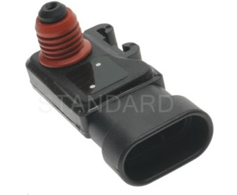
Manifold Absolute Pressure (MAP) Sensor
The manifold absolute pressure (MAP) sensor responds to changes in intake manifold pressure (vacuum). The MAP sensor signal voltage to the PCM
varies from below 2 volts at idle (high vacuum) to above 4 volts with the ignition ON, engine not running or a wide-open throttle (low vacuum).
The MAP sensor is used to determine the following:
- Manifold pressure changes while the linear EGR flow test diagnostic is being run.
- Engine vacuum level for other diagnostics
- Barometric pressure (BBRO)
If the PCM detects a voltage that is lower than the possible range of the MaP sensor, DTC P0107 will be set. A signal voltage higher that the possible
range of the sensor will set DTC P0108. An intermittent low or high voltage will set DTC P1107 or DTC P1106, respectively.
The PCM can detect a shifted MAP sensor. The PCM compares the MAP sensor signal to a calculated MAP based on throttle position and various engine
load factors.
If the PCM detects a MAP signal that varies excessively above or below the calculated value, DTC P0106 will set
Powertrain Control Module (PCM
This sensor is located in the passenger compartment below the center console. The PCM controls the following:
- Fuel metering system
- Transmission shifting (automatic transmission only)
- On-board diagnostics for powertrain functions
- Ignition timing
The PCM constantly observes the information from various sensors. The PCM controls the systems that affect vehicle performance. The PCM performs
the diagnostic function of the system. It can recognize operational problems, alert the driver through the MIL (Service Engine soon Lamp), and store
diagnostic trouble codes (DTCs). DTCs identify the problem areas to aid the technician in making repairs.
This engine uses 2 different control modules
- IPCM-69KT for automatic Transmission-equipped vehicles
- ISFI-6for manual Transmissions-equipped vehicles
PCM Function
The PCM supplies either 5 or 12 volts to power various sensors or switches. The power is supplied through resistances in the PCM which are so high in
value that a test light will not light when connected to the circuit. In some cased, even an ordinary shop voltmeter will not give an accurate reading
because its resistance is too low.
Therefore, a digital voltmeter with at least 10 meg-ohms input impedance is required to ensure accurate voltage readings. Tool J39200 meets this
requirement. The PCM controls output circuits such as the injectors, IAC, cooling fan relays, etc., by controlling the ground or the power feed circuit
through transistors of following device.
- Output Driver Module (ODM)
PCM Components
The PCM is designed to maintain exhaust emission levels to government mandated standards while providing excellent drivability and fuel efficiency.
The PCM monitors numerous engine and vehicle functions via electronic sensors such as the throttle position (TP) sensor, heated oxygen sensor (Ho2S),
and vehicle speed sensor (VSS). The PCM also controls certain engine operations through the following:

- Fuel injector control
- Ignition control module
- Knock sensor
- Automatic transmission shift functions
- Cruise control
- A/C clutch control
PCM Voltage Description
The PCM supplies a buffered voltage to various switches and sensors. It can do this because resistance in the PCM is so high in value that a test light may
not illuminate when connected to the circuit. An ordinary shop voltmeter many not give an accurate reading because the voltmeter input impedance is
too low. Use a 10-meg-ohm input impedance digital voltmeter (such as J 39200) to assure accurate voltage readings.
The input/output devices in the PCM include analog-to-digital converters, signal buffers, counters, and special drivers. The PCM controls most component
with electronic switches which complete a ground circuit when turned “ON”. These switches are arranged in groups of 4 and 7, called either a
surface-mounted quad driver module (QDM), which can independently control up to 4 output terminals, or QDMs which can independently control up
to 7 outputs. Not all outputs are always used.
PCM Input/Outputs
- Inputs-Operating Conditions Read
- Air Conditioning “ON” or “OFF”
- Engine Coolant Temperature
- Crankshaft Position
- Exhaust Oxygen Content
- Electronic Ignition
- Manifold Absolute Pressure
- Battery Voltage
- Throttle Position
- Vehicle Speed
- Fuel Pump Voltage
- Power Steering Pressure
- Intake Air Temperature
- Mass Air Flow
- Engine Knock
- Camshaft Position
Outputs-Systems Controlled
- Exhaust Gas Recalculation (EGR)
- Ignition Control
- Fuel Control
- Idle Air Control
- Electric Fuel Pump
- Air Conditioning
- Diagnostic
--Malfunction Indicator Lamp (Service Engine Soon Lamp)
--Data Link Connector (DLC)
--Data Output
- Transmission Control Module
- Alternator Gain Control
PCM Service Precautions
The PCM is designed to withstand normal current draws associated with vehicle operation. Avoid overloading any circuit. When testing for opens and
shorts, do not ground or apply voltage to any of the PCM’s circuits unless instructed to do so. These circuits should only be tested Tech-2.
The PCM should remain connected to the PCM or to a recommended breakout box.
Reprogramming the PCM
The Trooper allows reprogramming of the PCM without removing it from the vehicle. This provides a flexible and cost-effective method of making
changes I software calibrations.
The service programming system (SPS) will not allow incorrect software programming or incorrect calibration changes.
Throttle Position (TP) Sensor
The throttle position sensor is a potentiometer connected to the throttle shaft on the throttle body. The PCM monitors the voltage on the signal line and
calculates throttle position. AS the throttle valve angle is changed (accelerator pedal moved), the TP sensor signal also changes. At a closed throttle
position, the output of the TP sensor is low. As the throttle valve opens, the output increases so that a wide open throttle (WOT), the output voltage
should be about 4 volts.
The PCM calculates fuel delivery based on throttle valve angle (driver demand). A broken or loose TP sensor may cause intermittent bursts of fuel from
an injector and unstable idle because the PCM thinks the throttle is moving. A hard failure in the TP sensor 5-volt reference or signal circuits will set a
DTC P0123. A hard failure with the TP sensor ground circuit may set DTC P0123. Once a DTC is set, the PCM will use an artificial default value based on
engine RPM and mass air flow for the throttle position, and some vehicle performance will return. A high idle may result when DTC P0123 is set.
The PCM can also detect a shifted TP sensor. The PCM monitors throttle position and compares the actual TP sensor reading to a predicted TP value
calculated from engine speed. If the PCM detects an out-or-range condition, DTC P0121 will be set
Transmission Fluid Temperature (TFT) Sensor
The transmission fluid temperature sensor is a thermostat which changes its resistance based on the temperature of the transmission fluid.
A failure in the TFT sensor or associated wiring will cause DTC P0712 or DTC P0723 to set. In this case, engine coolant temperature will be substituted
for the TFT sensor value and the transmission will operate normally.

Circuit Description
The automatic transmission fluid temperature (TFT) sensor is part of the automatic transmission fluid pressure (TFP) manual valve position switch.
The TFT sensor is a resistor, or thermostat, which changes value based on temperature. The sensor has a negative-temperature coefficient. This means
that as the temperature increases, the resistance decreases, and as the temperature decreases, the resistance increases. The powertrain control module
(PCM) supplies a 5-volt reference signal to the sensor on circuit 1227 and measures the voltage drop in the circuit. When the transmission fluid is cold,
the sensor resistance is high and the PCM detects high signal voltage. As the fluid temperature warms to a normal operating temperature, the resistance
becomes less and the signal voltage decreases. The PCM uses this information to control shift quality and torque converter clutch apply.
When the PCM detects a continuous short to ground in the TFT signal circuit or in the TFT sensor, then DTC P0712 sets. DTC P0712 is a type C DTC.
Transmission Range Switch
IMPORTANT: The vehicle should not be driven with the transmission range switch disconnected; idle quality will be affected.
The four inputs from the transmission range switch indicate to the PCM which position is selected by the transmission selector lever. This information is
used for ignition timing, EVAP canister purge, EGR and IAC vale operation
|
 Facebook us @
 Twitter us @